6.1.1 Control device locations
Figure 1. Buster M1/M2
helm station controls
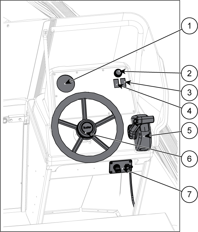
1 | Tachometer | 5 | Remote control |
2 | 12 V outlet | 6 | Steering wheel |
3 | Navigation lights switch | 7 | Power and start switch and emergency cut-off switch |
4 | Bilge pump switch |
Figure 2. Buster M1/M2
helm station controls with Buster Q
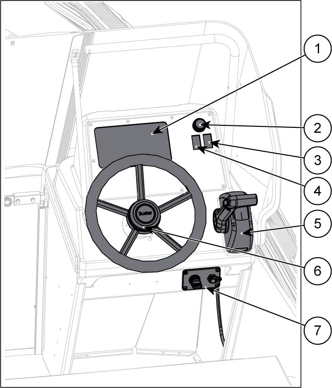
1 | Buster Q | 5 | Remote control |
2 | 12 V outlet | 6 | Steering wheel |
3 | Navigation lights switch | 7 | Power and start switch and emergency cut-off switch |
4 | Bilge pump switch |