9.2.1 Switch and fuse descriptions
Figure 1. Buster Magnum
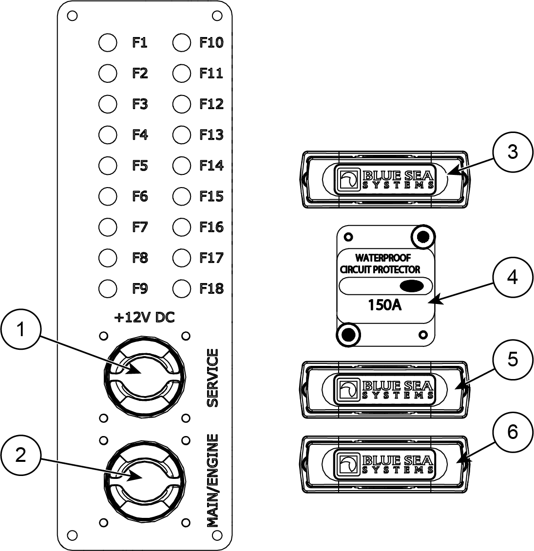
Cabin main switches and fuse panel
Position |
Description |
Amperage |
Position |
Description |
Amperage |
|---|---|---|---|---|---|
1 |
Main switch service |
F7 |
Power steering |
60 A |
|
2 |
Main switch engine |
F8 |
Buster Q |
5 A |
|
3 |
Isolator |
60 A |
F9 |
Bilge pump |
5 A |
4 |
Anchor winch |
150 A |
F10 |
Search light |
15 A |
5 |
Bow thruster |
250 A |
F11 |
Deck lights, roof lights, horn |
10 A |
6 |
Service |
250 A |
F12 |
Driving lights |
10 A |
F1 |
Antenna amp |
3 A |
F13 |
Extra |
10 A |
F2 |
NMEA |
3 A |
F14 |
Anchor winch remote |
5 A |
F3 |
Radar |
5 A |
F15 |
Outlet |
15 A |
F4 |
Navigation lights |
5 A |
F16 |
Fridge |
15 A |
F5 |
Wipers |
10 A |
F17 |
Heater |
20 A |
F6 |
Trims |
20 A |
F18 |
Extra / Audio |
50 A |